


Related
Documentation
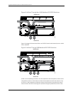
See Rear Panel of an EX2200 Switch on page 6 for port location.•
• See Rear Panel of an EX3200 Switch for port location.
• See Rear Panel of an EX4200 Switch for port location.
• See Front Panel of an EX4500 Switch for port location.
• See Switch Fabric and Routing Engine (SRE) Module in an EX8208 Switch for port
location.
• See Routing Engine (RE) Module in an EX8216 Switch for port location.
• Booting an EX Series Switch Using a Software Package Stored on a USB Flash Drive
Network Port Connector Pinout Information for an EX2200 Switch
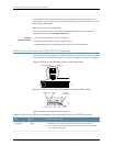
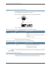
A network port on an EX2200 switch uses an RJ-45 connector to connect to a device.
The port uses an autosensing RJ-45 connector to support a 10/100/1000Base-T
connection. Two LEDs on the port indicate link/activity on the port and the port status.
See “Network Port and Uplink Port LEDs in EX2200 Switches” on page 12.
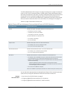
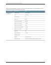
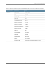
Table 10 on page 20 provides the pinout information for the RJ-45 connector. An RJ-45
cable, with a connector attached, is supplied with the switch.
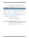
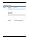
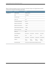
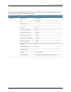
Table 10: Network Port Connector Pinout Information for EX2200 Switches
DescriptionSignalPin
Transmit/receive datapair 1
NegativeVport(in PoEmodels)
TRP1+1
Transmit/receive datapair 1
NegativeVport(in PoEmodels)
TRP1-2
Transmit/receive datapair 2
Positive Vport (in PoEmodels)
TRP2+3
Transmit/receive datapair 3TRP3+4
Transmit/receive datapair 3TRP3-5
Transmit/receive datapair 2
Positive Vport (in PoEmodels)
TRP2-6
Transmit/receive datapair 4TRP4+7
Transmit/receive datapair 4TRP4-8
Copyright ©2010,Juniper Networks,Inc.20
CompleteHardwareGuide forEX2200 EthernetSwitches