


•
Serial number ID label
•
AC power cord inlet
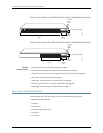
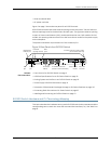
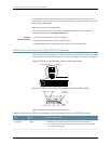
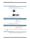
Figure 3 on page 7 shows the rear panel of an EX2200 switch.
All EX2200 switches have three exhaust openings on the rear panel. The two leftmost
exhaust openings have fans behind them and are open. The rightmost exhaust opening
is open on Power over Ethernet (PoE) models and closed on non-PoE models. On PoE
models, this opening exhausts the air from the fan at the air intake for the power supply
on the side panel.
The power cord retainer clips extend out of the chassis by 3 in.
Figure 3: Rear Panel of an EX2200 Switch
g027001
USB
port
Management
Ethernet port
Console
port
Protective
earthing terminal
Air exhaust without fan
(closed on non-PoE models)
Air exhaust
with fan
AC power
cord inlet
ESD
point
EX2200-24-4GREV:X1
750-026464REV:X3
MAC:00:23:9C:oE:19:00
Mfg.Date
20090227
MADEINCHINA
Serial number
ID label
Air intake with fan for power supply
(fan on PoE models only)
Related
Documentation
Front Panel of an EX2200 Switch on page 5•
• USB Port Specifications for an EX Series Switch on page 19
• Cooling System and Airflow in an EX2200 Switch on page 15
• Power Supply in EX2200 Switches on page 14
• Prevention of Electrostatic Discharge Damage on EX Series Switches on page 142
• Connecting Earth Ground to an EX Series Switch on page 67
• Installing and Connecting an EX2200 Switch on page 51
EX2200 Switch Hardware and CLI Terminology Mapping
Thistopic describes the hardware terms used in EX2200 switch documentationand the
corresponding terms used in the Junos OS command line interface (CLI). See Table 3 on
page 8.
7Copyright©2010, JuniperNetworks, Inc.
Chapter1:EX2200 SwitchOverview