


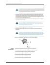
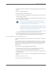
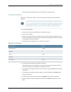

4. Push the power cord into the slot in the adjustment nut of the power cord retainer
clip. Turnthe nut until it is tight against the base of the coupler and the slot in the nut
is turned 90° from the top of the switch (see Figure 28 on page 74).
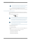
5. If the AC power source outlet has a power switch, set it to the OFF (0) position.
6. Insert the power cord plug into an AC power source outlet.
7. If the AC power source outlet has a power switch, set it to the ON (|) position.
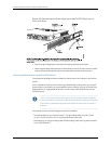
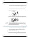
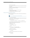
Figure 27: Connecting an AC Power Cord Retainer Clip to the AC Power
Cord Inlet on an EX2200 Switch
g027013
Retainer clip
Adjustment nut
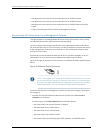
Figure 28: Connecting an AC Power Cord to the AC Power Cord Inlet on
an EX2200 Switch
g027014
Tighten
adjustment nut.
Related
Documentation
Connecting and Configuring an EX Series Switch (CLI Procedure) on page 87•
• Connecting and Configuring an EX Series Switch (J-WebProcedure) on page 89
• Power Supply in EX2200 Switches on page 14
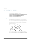
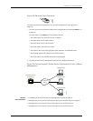
Connecting an EX Series Switch to a Network for Out-of-Band Management
This topic applies to multiple hardware devices in the EX Series product family, which
includes switches and the XRE200 External Routing Engine.
You can monitor and manage these devices using a dedicated management channel.
Each device has a management port with an RJ-45 connector for out-of-band
management. Use the management port to connect the EX Series switch or external
Routing Engine to the management device.
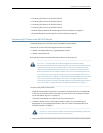
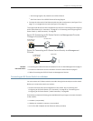
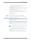
Ensure that you have an Ethernet cable with an RJ-45 connector available. One such
cable is provided with the device. Figure 29 on page 75 shows the RJ-45 connector of
the Ethernet cable supplied with the device.
Copyright ©2010,Juniper Networks,Inc.74
CompleteHardwareGuide forEX2200 EthernetSwitches