


•
Remove the switch from the shipping carton (see “Unpacking an EX2200 Switch” on
page 52).
Ensure that you have the following parts and tools available:
•
2 wall-mount brackets (provided in the wall-mount kit)
•
1 wall-mount baffle (provided in the wall-mount kit)
•
12 wall-mount bracket screws (provided in the wall-mount kit)
•
6 mounting screws (8-32 x 1.25 in. or M4 x 30 mm) (not provided)
•
Hollow wall anchors rated to support up to 75 lb (34 kg) if you are not screwing the
screws directly into wall studs (not provided)
•
Phillips (+) screwdriver, number 2 (not provided)
To mount one or two switches on a wall:
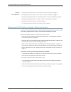
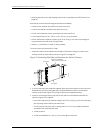
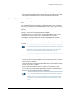
1. Attach the wall-mount brackets to the sides of the chassis using four wall-mount
bracket screws on each side, as shown in Figure 21 on page 62.
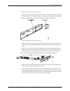
Figure 21: Attaching Wall-Mount Brackets to a Switch Chassis
g027022
Front panel
Rear panel
Baffle for PoE Models
(EX2200-24P and EX2200-48P)
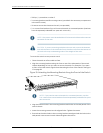
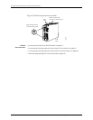
2. If you are mounting two switches together, align the second switch on top of the first
and attach it to the mounting brackets using two additional wall-mount bracket
screws on each side (Figure 23 on page 64 shows two aligned switches).
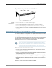
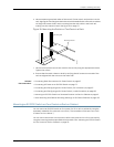
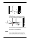
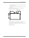
3. Install six mounting screws in the wall for the wall-mount brackets and baffle as
shown in Figure 22 on page 63:
•
Use hollow wall anchors rated tosupport up to75 lb (34 kg) if you are not inserting
the mounting screws directly into wall studs.
•
Turnthe screws only part way in, leaving about 1/4 in. (6 mm) distance between
the head of the screw and the wall.
a. Install screw A.
b. Install screw B 18.68 in. (47.4cm) from screw A on a level line.
Copyright ©2010,Juniper Networks,Inc.62
CompleteHardwareGuide forEX2200 EthernetSwitches