


• Connecting an EX Series Switch to a Management Console on page 76
Management Port Connector Pinout Information for an EX2200 Switch
The management port on an EX2200 switch uses an RJ-45 connector to connect to a
management device for out-of-band management.
The port uses an autosensing RJ-45 connector to support a 10/100Base-T connection.
Two LEDs on the port indicate link/activity on the port and the administrative status of
the port. See “Management Port LEDs in EX2200 Switches” on page 14.
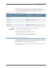
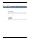
Table 12 on page 22 provides the pinout information for the RJ-45 connector for the
managementport.AnRJ-45cable,withaconnectorattached,issuppliedwiththeswitch.
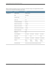
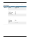
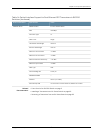
Table 12: Management Port Connector Pinout Information for EX2200 Switches
DescriptionSignalPin
Transmit/receive datapair 1TRP1+1
Transmit/receive datapair 1TRP1-2
Transmit/receive datapair 2TRP2+3
Transmit/receive datapair 2TRP2-6
Related
Documentation
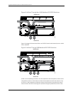
See Rear Panel of an EX2200 Switch on page 6 for port location.•
• ConnectinganEXSeriesSwitchtoaNetworkforOut-of-BandManagementonpage74
Optical Interface Support in EX2200 Switches
Uplink ports on the front panel in EX2200 switches support SFP transceivers. This topic
describes the optical interfaces supported for those transceivers. It also lists the copper
interface supported for the SFP transceivers.
NOTE: Use onlyoptical transceiversand opticalconnectors purchased from
Juniper Networks for your EX2200 switch.
The two tables in this topic describe the optical interface support over single-mode
fiber-optic(SMF)andmultimodefiber-optic(MMF)cablesandoverthecopperinterface
for SFP transceivers:
•
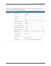
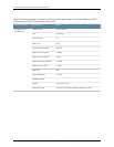
Table13onpage23—OpticalinterfacesupportandcopperinterfacesupportforGigabit
Ethernet SFP transceivers
•
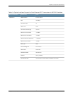
Table 14 on page 27—Optical interface support for Fast Ethernet SFP transceivers
Copyright ©2010,Juniper Networks,Inc.22
CompleteHardwareGuide forEX2200 EthernetSwitches