


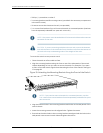
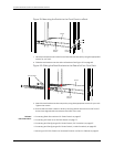
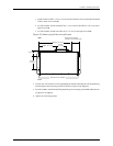


c. Install screw C 5.98 in. (15.2 cm) on a plumb line down from screw A and screw D
5.98 in. down from screw B.
d. For PoEmodels, install screwE 2.76in. (7 cm) up from and 8.32 in. (21.1cm) to the
right of screw A.
e. For PoE models, install screw F 4.49 in. (11.4 cm) to the right of screw E.
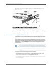
Figure 22: Measuring for Mounting Screws
18.68 in. (47.4 cm)
Front
Rear
A
E F
C
B
D
Side wall-mount brackets
8.32 in. (21.1 cm)
4.49 in.
(11.4 cm)
5.98 in.
(15.2 cm)
2.76 in (7 cm)
g021067
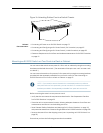
Baffle for PoE Models
(EX2200-24P and EX2200-48P)
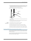
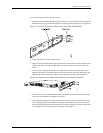
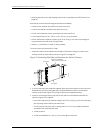
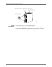
4. Liftthe unit (one switchor two) by grasping eachside, and hang the unit byattaching
the brackets to the mounting screws as shown in Figure 23 on page 64.
5. ForPoEmodels,installthebafflebyattachingittomountingscrewsEandFasshown
in Figure 23 on page 64.
6. Tighten all mounting screws.
63Copyright©2010,Juniper Networks,Inc.
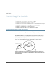
Chapter8:Installing theSwitch