


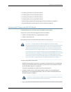

Figure 29: Ethernet Cable Connector
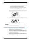
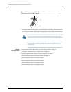
To connect a device to a network for out-of-band management (see Figure 30 on
page 75):
1. Connect one end of the Ethernet cable to the management port (labeled MGMT) on
the device.
For the location of the MGMT port on different devices:
•
See “Rear Panel of an EX2200 Switch” on page 6.
•
See Rear Panel of an EX3200 Switch.
•
See Rear Panel of an EX4200 Switch.
•
See Front Panel of an EX4500 Switch.
•
See Switch Fabric and Routing Engine (SRE) Module in an EX8208 Switch.
•
See Routing Engine (RE) Module in an EX8216 Switch.
•
See Front Panel of an XRE200 External Routing Engine.
2. Connect the other end of the Ethernet cable to the management device.
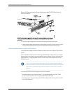
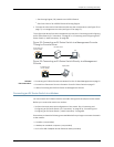
Figure 30: Connecting an EX Series Switch to a Network for Out-of-Band
Management
g020548
Management PC
Management PC
Management PC
ToManagement port
(on the switch)
Management
network
Related
Documentation
Connecting an EX Series Switch to a Management Console on page 76•
• Management Port Connector Pinout Information for an EX2200 Switch on page 22
• Management Port Connector Pinout Information for an EX3200 Switch
• Management Port Connector Pinout Information for an EX4200 Switch
75Copyright©2010,Juniper Networks, Inc.
Chapter10:Connectingthe Switch