ProSecure Unified Threat Management (UTM) Appliance Reference Manual
Introduction 1-11
v1.0, January 2010
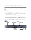
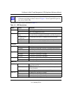
The function of each LED is described in Table 1-2.
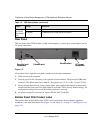
Note: Figure 1-2 shows a dual-WAN port model (the UTM25). Single-WAN port models
contain the left WAN port that is shown in Figure 1-2 but no right WAN port nor
any Active WAN LEDs.
Table 1-2. LED Descriptions
Object Activity Description
Power On (Green) Power is supplied to the UTM.
Off Power is not supplied to the UTM.
Test On (Amber) during
startup.
Test mode: The UTM is initializing. After approximately 2 minutes,
when the UTM has completed its initialization, the Test LED goes off.
On (Amber) during
any other time
The initialization has failed or a hardware failure has occurred.
Blinking (Amber) Writing to flash memory (during upgrading or resetting to defaults).
Off The system has booted successfully.
LAN Ports
Left LED Off The LAN port has no link.
On (Green) The LAN port has detected a link with a connected Ethernet device.
Blink (Green) Data is being transmitted or received by the LAN port.
Right LED Off The LAN port is operating at 10 Mbps.
On (Amber) The LAN port is operating at 100 Mbps.
On (Green) The LAN port is operating at 1000 Mbps.
DMZ LED Off Port 4 is operating as a normal LAN port.
On (Green) Port 4 is operating as a dedicated hardware DMZ port.
WAN Ports
Left LED Off The WAN port has no physical link, that is, no Ethernet cable is
plugged into the UTM.
On (Green) The WAN port has a valid connection with a device that provides an
Internet connection.
Blink (Green) Data is being transmitted or received by the WAN port.
Right LED Off The WAN port is operating at 10 Mbps.
On (Amber) The WAN port is operating at 100 Mbps.
On (Green) The WAN port is operating at 1000 Mbps.


