Page: 153
Service Guide OJ2010
Chapter A Board Diagrams
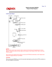
A.3.02 Checkpoint Locations
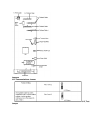
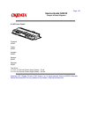
Paper Feed Motor
1. Disconnect the paper feed motor cable (J5) from the system board.
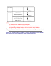
2. Check the resistance between the motor pins listed below.
Pin 1 to Pin 4 100 ohms (+ / - 20 ohms)
Pin 2 to Pin 4 100 ohms (+ / - 20 ohms)
Pin 3 to Pin 5 100 ohms (+ / - 20 ohms)
Pin 3 to Pin 6 100 ohms (+ / - 20 ohms)
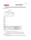
Transport Motor
1. Disconnect the transport motor cable (J6) from the system board.
2. Check the resistance between the motor cable pins listed below.
Pin 2 to Pin 3 8 to 18 ohms
Copyright 1997, Okidata, Division of OKI America, Inc. All rights reserved. See the OKIDATA Business
Partner Exchange (BPX) for any updates to this material. (http://bpx.okidata.com)


