


Page: 74
Service Guide OJ2010
Chapter 3 Maintenance and Disassembly
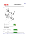
3.2.17 Left Side Frame Assembly
1. Remove the preliminary items. . . . . . . . . . (3.2.01 ( ))
2. Remove the front cover. . . . . . . . . . . . . . . . (3.2.12 (
))
3. Remove the rear cover. . . . . . . . . . . . . . . . (3.2.30 (
))
4. Remove the carrier frame assembly. . . . (3.2.04 (
))
5. Remove the paper load door. . . . . . . . . . . (3.2.24 (
))
6. Remove the manual insert tray. . . . . . . . . . (3.2.20 (
))
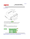
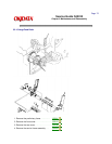
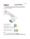
7. Use a small straight-slot screwdriver to break the four prongs of the small compound idler gear (1).
8. Remove the gear.
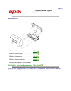
NOTE:
Note the installation of the parts in the next two steps.
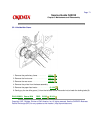
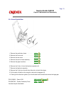
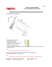
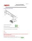
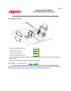
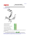
9. Remove the two screws (2) securing the left side frame (3) to the back plate (4).
10. Slide the left side frame off the back plate.
NOTE:
Install the new compound idler gear after the machine is installed in the base assembly.
P/N 53347401 Assembly: Left Side Frame Sub RSPL B.2.03 w/o Gears
P/N 53347801 Frame: Back Plate Extrusion RSPL B.2.08