


4. Troubleshooting 1000-A2-GN22-00
4-6 February 2003
Table 4–3 lists the modules and indicator states for normal
operating conditions.
Module
Troubleshooting
Before performing a module fault isolation:
1. Verify that the board and each component is securely seated.
MAJOR
indicator on
(continued)
PSTN Remote failure indication - line
Bit Error Ratio - signal fail or degraded
Remove failure indication - STS path\
Alarm indication signal - VT
Loss of pointer or unequipped VT
Payload label mismatch - VT
T1 Ports PSTN Alarm indication signal - DS1
PSTN Remote Alarm indication - DS1
MINOR
indicator on
IAD Provisioned compression scheme(s) not supported
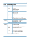
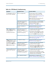
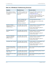
Table 4–2. Telco Status Indicators (Continued)
Symptom Possible Cause Further Isolation of Alarm
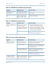
Table 4–3. Normal Activity Indicator Usage
Module Normal Usage
ATM Active ATM modules have ACTive lit; standby module lights not lit
CP/HSC Active CP/HSC module have
ACTive lit; standby module lights not lit
EC All unlocked EC modules are lit
ECAC All unlocked ECAC modules are lit
MP
ACTive always lit
T1 All unlocked T1 modules are lit
STS-1 Active STS-1 modules have
ACTive lit; standby module lights not lit
Warning
Take care not to damage or bend the connector pins, and
avoid touching areas of integrated circuits.