


Index 1000-A2-GN22-00
I-2 February 2003
Control Processors
troubleshooting
4-7, 4-8
controls and indicators, ACE module 2-33
CP module
Ethernet LAN connections
3-25
hot swap 5-11
troubleshooting 4-7, 4-8, 4-11
CPX-1000
assigning IP address
3-34
attaching power source to 3-16, 3-17
connection requirements B-2
features of 2-2
grounding 3-17
installing multiple 3-7
NEBS requirements D-1
overview of system 3-8
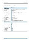
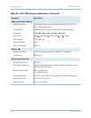
physical layer specifications B-2
powering up 3-32
safety precautions 3-5
shelf, specifications of 2-10
specifications D-1
D
data interruptions -ix
data transmission indicators 2-33
default IP address 3-34
distribution panels 3-8
dry relay contacts B-7
DS1 ports 2-27, 2-29
DS-3
specifications
B-2
E
ECAC 2-36
Echo Cancellation and Compression Module 2-36
Echo Cancellation Module 2-35
status indicator for 2-35
EIA310 racks 3-8, 3-12
electrical hazards -ix, 3-16, 5-2
environmental requirements 3-7
equipment racks 3-8
attaching mounting flanges 3-12
mounting the STS-1 Splitter Assembly 3-16
power requirements 3-8
ESD damage, preventing 3-5
Ethernet LANs B-2
attaching JetCraft terminals to 3-34
connections 3-25
PING testing 3-35
troubleshooting 4-11
verifying port operation 3-34
Ethernet module
pin assignments
B-4, B-8
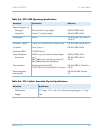
Ethernet specifications B-3
external alarms B-4, B-7, D-4
F
failure detection B-7
fans
checking
3-34
power supplies 3-34
troubleshooting 5-2
fatality precautions -ix, 5-2
faulty cabling 4-11
fiber optic cables 3-32
fiber optic network connections 3-24
frame ground B-2
frame grounding cable 3-17
fuses 3-8
G
GR-303, support for in STS-11 Module 2-26, 2-29
GR-303, support for in T1 Module 2-20
ground requirements B-4
grounding cable 3-17
H
hazards 3-16
host Class 5 switches B-2
connecting to 3-26, 3-29, 3-30
hot swapping
CP cards
5-11
HSC cards 5-11
line cards 5-11
MP card 5-10
HSC cards, hot swap 5-11
humidity 3-7
I
indicator states 3-33