


B. Pin Assignments and Indicators 1000-A2-GN22-00
B-4 February 2003
Ethernet LAN
(10Base-T or 100Base-T)
Physical interface: CAT-5 or equivalent cable
Termination: RJ-45 plug
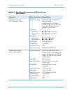
Bonding network environment Common, integrated ground plane, multi-point ground.
–48 VDC plant battery and return Minimum 14 AWG wires (total of four), stranded or
solid; up to 40 feet maximum from the plant battery
distribution point.
Terminate using LCC or LCD compression lugs (with
two #10 screw holes).
Range:
40 VDC to 72 VDC
Turn On:
38.5V to 41V
Turn On surge current: 40A (with two power supplies
installed) at
40 VDC, for duration <4 ms
Frame ground Stranded copper wire; must be larger than the wire size
used for –48V power and ground wiring (6 AWG
recommended). This cable must be fitted with a Type
LCC or LCD dual-lug compression connector on one
end, for attachment to the CPX-1000 shelf.
All connections must be tin-coated copper crimp lugs.
Alarm output connections 22-gauge solid wire for dry contact closures to an
external alarm monitoring system.
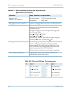
Table B–1. Connection Requirements and Physical Layer
Specifications (Continued)
Connections Cables, Connectors, and Specifications
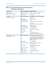
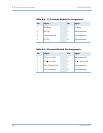
Table B–2. Ethernet LAN Jack Pin Assignments
Pin Signal Pin Signal
1 Tx (+) to LAN 5Not connected
2Tx (
) to LAN 6Rx () from LAN
3 Rx (+) from LAN
7Not connected
4Not connected
8Not connected