


4. Troubleshooting 1000-A2-GN22-00
4-12 February 2003
Power System
Troubleshooting
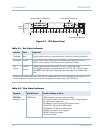
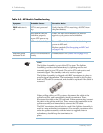
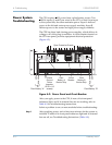
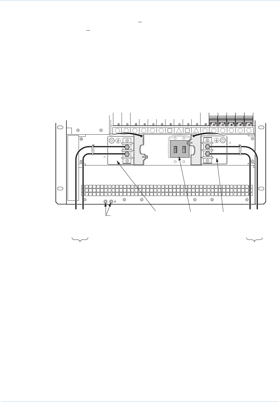
The CPX requires 48V power from a plant battery source. Two
48Vdc inputs (A and B) are wired to the CPX, so that if one input
to the system fails, the other maintains power. Input A delivers
power to the left and center power supply modules; Input B
delivers power to the center and right power supply modules.
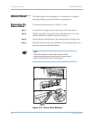
The CPX has three load-sharing power supplies, which deliver dc
voltage to all of the plug-in modules. A circuit breaker located on
the CPX rear panel, provides equipment electrical protection
(Figure 4–2).
Figure 4–2. Power Panel and Circuit Breaker
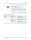
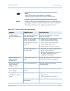
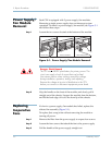
After you apply power to the CPX, if none of its front panel
indicators light, and if its internal fans are not working, refer to
Table 4–9 for troubleshooting instructions.
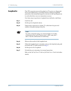
Isolate a problem to one or more modules before troubleshooting:
Step 1 After applying power, wait at least two minutes for the system to
initialize. If none of its front panel indicators light and its internal
fans are off, see Troubleshooting Instructions (Table 4–9).
0069
16 15 14 13 12 11
7
9
6
810
54321
DC -48V
DC -48V
RTN
DC -48V
DC -48V
RTN
To
Plant Battery "A"
-48V RTN
-48V
To
Plant Battery "B"
-48V
-48V RTN
Plant
Battery A
Barrier Strip
Frame
Ground
Points
(requires
10-32 x 1/4"
screws)
Circuit
Breaker
Plant
Battery B
Barrier Strip
Open Protective Guards