


February 2003 3-31
1000-A2-GN22-00 3. Installing the CPX-1000
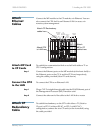
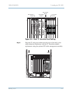
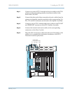
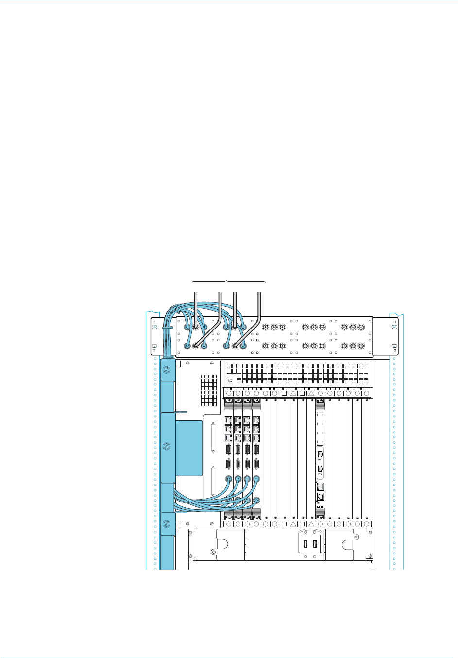
Step 1 Connect two pairs of STS-1 transmit and receive cables to the STS-1
primary and corresponding standby transition modules in the
back of the CPX shelf.
Step 2 Connect the other end of these transmit and receive cables from the
primary and standby transition modules to the corresponding Tx1,
Rx1, Tx2 and Rx2 connectors on the back of the Splitter Assembly.
Step 3 Connect a pair of STS-1 transmit and receive cables to the TO NET
and FROM NET connectors of the STS-1 Splitter Assembly.
Step 4 Connect the transmit and receive cables to the corresponding
connectors on the Class 5 switch.
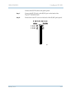
Step 5 Dress the STS-1 and power cables from the rear of the shelf, so the
cables run in a manner that minimizes interference with STS-1
Transition module replacement.
16 15 14 13 12 11
7
9
6
810
54321
16 15 14 13 12 11
7
9
6
810
54321
ESD
BONDING
POINT
T
R
T
R
T
RS-232
PROT
SWITCH
TX
RX
RS-232
PROT
SWITCH
TX
RX
P
C
M
T
E
S
T
B
I
T
S
I
O
B
T
E
T
H
P
C
M
T
E
S
T
B
I
T
S
I
O
B
T
E
T
H
RS-232
PROT
SWITCH
TX
RX
RS-232
PROT
SWITCH
TX
RX
P
C
M
T
E
S
T
B
I
T
S
I
O
B
T
E
T
H
P
C
M
T
E
S
T
B
I
T
S
I
O
B
T
E
T
H
TX1
TO NET
TX2
RX1
FROM NET
RX2
TX1
TO NET
TX2
RX1
FROM NET
RX2
TX1
TO NET
TX2
RX1
FROM NET
RX2
TX1
TO NET
TX2
RX1
FROM NET
RX2
TX1
TO NET
TX2
RX1
FROM NET
RX2
Coaxial Cables
to/from Class 5 Switch
RESET
EXT
ETHERNET
P
M
C
1
P
M
C
2
COM 1
PWR
10/100
ETHERNET
LNK
ACT
1
LNK
ACT
2