


February 2003 5-7
1000-A2-GN22-00 5. Repair Procedures
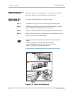
Step 2 Tighten the four captive screws in the corners of the panel.
Step 3 Replace the power cable.
Step 4 Turn on the CPX.
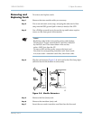
Module
Removal and
Installation
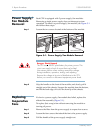
Use this procedure to replace a CPX plug-in module by removing
it from the shelf and installing another module.
The cards must first be removed from service using a network
management system (JetCraft or JetVision).
Review and perform the steps in Hot Swapping on page 5-10.
Caution
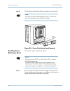
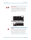
If the panel does not fully insert, do not force it—forcing it can
bend the connector pins. Instead, back the panel out, verify
that the connectors are aligned properly, and re-insert it.
CAUTION
CLASS 1 LASER
Use of controls, adjustment, or performance of
procedures other than those specified herein may result
in hazardous, invisible radiation exposure.
Module panel indicators are Class 1 LED products.
Warning
Some CPX components include field-replaceable batteries. A
new battery can explode if incorrectly installed. Replace the
battery only with the same or equivalent type recommended
by the manufacturer. Discard batteries according to the
manufacturer's instructions.