


3. Installing the CPX-1000 1000-A2-GN22-00
3-20 February 2003
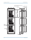
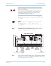
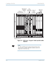
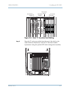
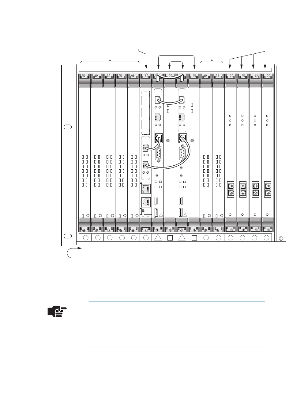
Figure 3–1. CPX Front—12-port T1 ECAC and OC-3 ATM
Modules
0482
123456 8 10
7
9
11 12 13 14 15 16
PWR
ERROR
PWR
ERROR
P
M
C
1
RESET
EXT
ETHERNET
P
M
C
2
COM 1
PWR
10/100
ETHERNET
LNK
2
ACT
LNK
1
ACT
Status
Tx
Rx
ATM 155
Status
Tx
Rx
ATM 155
Status
Tx
Rx
ATM 155
Status
Tx
Rx
ATM 155
BFL
RST
CPCI
USB 1COM 110/100 BASE T USB 0
CPU
PCI
ABT
PCI MEZZANINE CARD
10/100
ETHERNET
LNK
2
ACT
LNK
1
ACT
CP2
BFL
RST
CPCI
USB 1COM 110/100 BASE T USB 0
CPU
PCI
ABT
PCI MEZZANINE CARD
10/100
ETHERNET
LNK
2
ACT
LNK
1
ACT
CP2
1 2 3 4 5 6 7 8 9 10 11 12 13 14 15 16
Slot Numbers
12-Port T1
ECAC Modules
12-Port T1
ECAC
Modules
Management
Processor
Module
ATM OC-3
Modules
Call
Processor
Module Sets
HOT
SWAP
4
8
3
7
2
6
1
5
11 12
910
S
A
T
T
A
T
C
TDM-12E1/T1
HOT
SWAP
4
8
3
7
2
6
1
5
11 12
910
S
A
T
T
A
T
C
TDM-12E1/T1
HOT
SWAP
4
8
3
7
2
6
1
5
11 12
910
S
A
T
T
A
T
C
TDM-12E1/T1
HOT
SWAP
4
8
3
7
2
6
1
5
11 12
910
S
A
T
T
A
T
C
TDM-12E1/T1
HOT
SWAP
4
8
3
7
2
6
1
5
11 12
910
S
A
T
T
A
T
C
TDM-12E1/T1
HOT
SWAP
4
8
3
7
2
6
1
5
11 12
910
S
A
T
T
A
T
C
TDM-12E1/T1
HOT
SWAP
4
8
3
7
2
6
1
5
11 12
910
S
A
T
T
A
T
C
TDM-12E1/T1
Note
T1 cards and MP cards are paired with transition cards
(rear), to form a module. All other modules consist of a
single card, in the front only.