


3. Installing the CPX-1000 1000-A2-GN22-00
3-34 February 2003
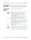
Step 9 Echo Cancellation Indicators: Verify that the Hot Swap
indicator is not lit. The STATUS indicator lights yellow when the
CPX is using the module.
Step 10 Echo Cancellation and Compression Module Indicators:
Verify that the Hot Swap indicator is not lit. The STATUS indicator
lights yellow when the CPX is using the module.
Alarm Panel
Indicators
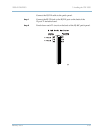
Check the Alarm panel indicators:
Step 1 Verify that the APP indicator flashes on and off continuously
(one second on, one second off).
Step 2 Verify that all of the system status indicators are off (they are
not used).
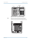
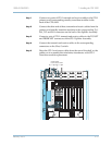
Check the Fans The two CPX Power Supply Fan modules are equipped with an
integral fan assembly, and a third fan is supplied for redundancy
(in case one of the other two fans fails).
Step 1 When power is first applied, the fans should run continuously,
circulating air through the system’s plug-in modules.
Step 2 Verify that the fans are running, and that the front vents on the
power supplies and the shelf rear vents are free of obstruction.
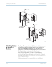
Verify Remote
Interface
The CPX requires a remote connection for remote management. To
verify the remote port operation after powering up the CPX,
perform these tasks:
Connect JetCraft
PC to CPX-1000
Make sure that JetCraft is installed on a PC. Connect the PC
directly to the ETHERNET 1 port on the MP transition card.
For this connection, use a CAT-5 crossover cable with RJ-45 plugs.
Change CPX
Default IP
Address
The default IP address for the CPX is:
IP address 10.0.10.100
subnet mask 255.255.0.0