


4. Troubleshooting 1000-A2-GN22-00
4-8 February 2003
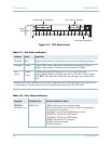
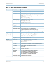
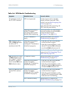
Table 4–5. MP Module Troubleshooting
Symptom Probable Causes Corrective Action
PWR indicator is
off.
CPX is not powered
up.
Verify that the CPX is receiving –48 VDC from
the plant battery.
MP module did not
initialize properly
upon CPX power-up.
Turn CPX rear circuit breaker off, then on
again to cycle power and reinitialize.
MP module is faulty. Ensure CP modules are initialized to bring
power to MP card.
Replace module (Hot Swapping an MP Card
on page 5-10).
Ethernet green
indicator is off.
MP-to-LAN interface is
faulty.
Troubleshoot LAN (Table 4–8 on page 4-11).
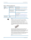
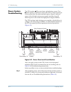
Note
The Splitter Assembly is part of the STS system. The Splitter
Assembly provides card redundancy by splitting receive and
transmit signal to two STS cards. The active STS card receive and
transmits signal. The standby card only receives signal.
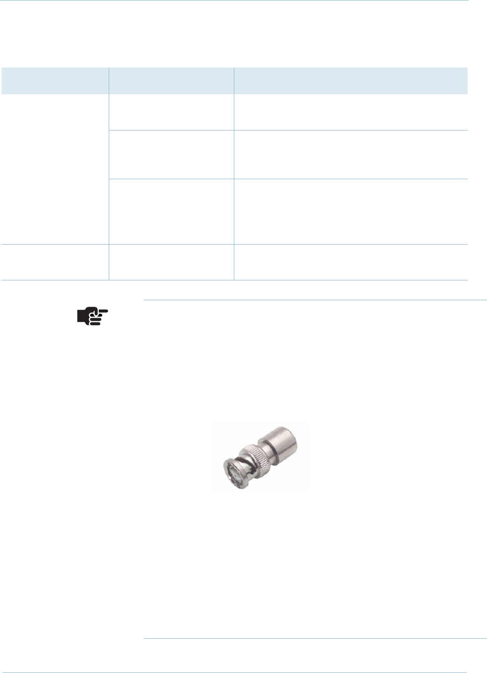
The Splitter Assembly is shipped with BNC terminators in place to
prevent signal degradation. The terminators should be left in place
until an STS cable is connected, and should be replaced if the cable is
removed.
When pulling cables on STS systems, disconnect the cable at the
splitter end first, and immediately install a terminator. Then,
disconnect the cable at the STS card end. When reconnecting, connect
the cable at the splitter end first. Then, remove the terminator at the
splitter assembly and immediately connect the STS cable.
The BNC terminators should also be used if the Splitter Assembly is
used in a non-redundant environment. For example, customers who
order the splitter assembly with the intent to upgrade later to
redundancy should keep the terminators in
place.