


Index 1000-A2-GN22-00
I-4 February 2003
remote alarm connector pin assignments B-7
remote system management 3-25
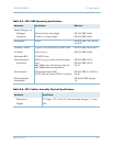
requirements
alarms
B-7
environment 3-7
power 3-8
racks 3-8
supplies 3-9
tools 3-9
reversing the mounting flanges 3-12
RTN A and RTN B terminals 3-18
RX indicator (ACE module) 2-33
S
safety precautions 3-5
shock 3-16
shock hazards -ix, 5-2
status indicator
ACE module
2-33
Alarm module 3-34
storage racks 3-8
attaching mounting flanges 3-12
mounting the STS-1 Splitter Assembly 3-16
power requirements 3-8
storage temperature and humidity 3-7
STS-1 Module
controls, indicators, and ports
2-27, 2-29
generally 2-25
supports GR-303 2-26, 2-29
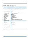
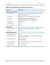
STS-1 PSTN Module
specifications
B-3
troubleshooting 4-9
STS-1 Splitter Assembly, mounting in rack 3-16
STS-1 splitter connections 2-31, 3-30
supplies required 3-9
system alarms B-7
system location 3-8
T
T1 connections 3-26, 3-29, 3-30, B-2
T1 Module 2-20
controls, indicators, and ports 2-23, 2-25
supports GR-303 2-20
T1 PSTN Module
specifications
B-3
troubleshooting 4-9
temperature 3-7
tools required 3-9
transit temperature and humidity 3-7
transition modules, indicator states 3-33
transmission indicators 2-33
turning on CPX-1000 3-32
TX indicator (ACE module) 2-33
V
VCI 2-7
ventilation 3-7
voice interruptions -ix
voltage levels 3-23
VPI 2-7
W
warnings 3-5, 5-3, 5-7, 5-8