


5. Repair Procedures 1000-A2-GN22-00
5-2 February 2003
Power Supply/
Fan Module
Removal
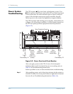
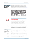
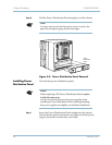
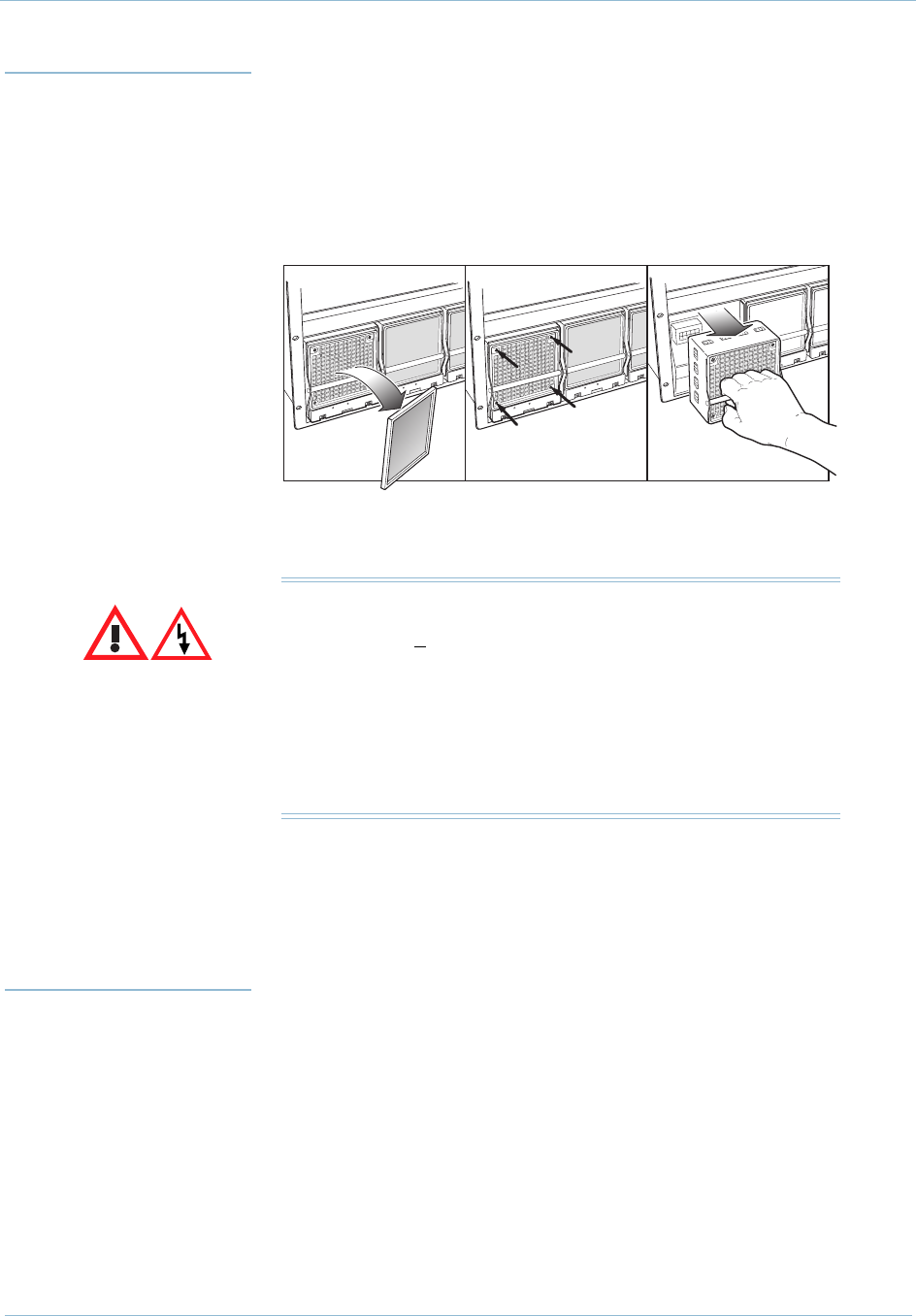
Each CPX is equipped with 3 power supply/fan modules.
Removing a single power supply does not interrupt system
operation. To remove a power supply/fan module, see Figure 5–1
and follow these steps:
Step 1 Loosen the two screws located at the bottom of the module.
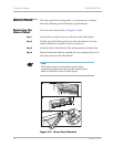
Figure 5–1. Power Supply/Fan Module Removal
Step 2 Grip the handle on the front of the module, and slowly pull it
straight out of the chassis. Support the module from the bottom,
and lift the back edge of it over the front lip of the chassis.
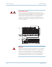
Replacing
Inoperative
Fans
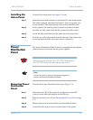
If a fan in a power supply/fan module has failed, replace the
affected fan assembly (Figure 5–1).
To replace (hot swap) a fan without removing the module or
turning off power:
Step 1 Remove the filter from the power supply to expose four screws.
Step 2 Loosen the four screws that attach the fan to the power supply.
Step 3 Pull the handle of the power supply straight out.
0178
Pull To Remove Fan
O
U
T
O
F
S
E
R
V
I
C
E
IN
S
E
R
V
I
C
E
OUT OF
SERVICE
IN
SERVICE
O
U
T
O
F
S
E
R
V
I
C
E
I
N
S
E
R
V
I
C
E
Lift Out Filter
OUT OF
SERVICE
IN
SERVICE
O
U
T
O
F
S
E
R
V
I
C
E
I
N
S
E
R
V
I
C
E
Remove 4 Screws
Danger: Shock Hazard
The CPX uses 48VDC plant battery for primary power. This
circuit can supply a level of current that can be fatal.
Use extreme caution when working around this voltage,
during installation, operation, testing, and adjusting.
Remove the voltage at its point of distribution to the CPX
before you connect or disconnect equipment power leads.