


February 2003 B-7
1000-A2-GN22-00 B. Pin Assignments and Indicators
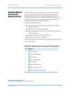
System Alarm
Connection
Requirements
The CPX-1000 includes an Alarm board in the summary alarm
panel at the top of the shelf. This Alarm board continuously
monitors various internal system operating parameters and
reports alarms (if failures are detected). Dry Form-A closures
1
are
provided for critical, major, and minor alarm connections to
external local alarm surveillance equipment.
The closure specifications are:
Rated resistive load: 20 Ohms (typical) @ 50 mA, 5 Ohms
(typical) @ 100 mA
Rated inductive load: not applicable
Operating voltage: 100 VDC/VAC (350 VDC or peak ac for
100 ms transients)
Continuous load: 250 mA dc, 150 mA ac
Minimum load: 10 A at 10mVDC
Critical alarm closure is normally closed. Major and minor closures
are normally open.
1. Optically coupled, CMOS FET bipolar switches
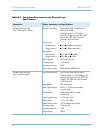
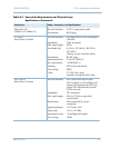
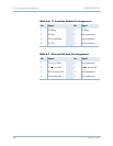
Table B–5. Remote Alarm Connector Pin Assignments
Pin Signal
1Critical Alarm
2 Critical Alarm Return
3Major Alarm
4Major Alarm Return
5Minor Alarm
6Minor Alarm Return
7 Rack Alarm (not used)
8 Rack Alarm Return (not used)