


February 2003 4-11
1000-A2-GN22-00 4. Troubleshooting
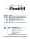
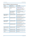
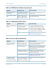
Secondary EOC PPS
Link is down
CPX and Class 5 switch
connection has been lost.
Verify that the interface group is active
in the switch.
Receive data on inactive
link
Switch and CPX do not
agree on which link is
active on TMC or EOC.
Have the switch force a PPS switch on
the TMC or EOC link.
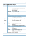
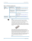
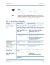
Table 4–7. ATM Module Troubleshooting
Symptom Probable Causes Corrective Action
Tx and/or Rx indicators
are off.
Software error occurred
on the CP module,
causing the ATM module
to initialize improperly.
1. Turn the CPX-1000 rear circuit
breaker switch off, then on again.
2. After the system initializes, verify
that the ATM module
Tx and/or Rx
indicators are lit or flashing.
ATM module is faulty. Replace the ATM module (see Module
Troubleshooting on page 4-6).
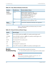
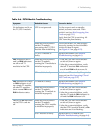
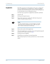
Table 4–8. Ethernet LAN Troubleshooting
Symptom Probable Causes Corrective Action
Ethernet link (green)
indicator is not lit.
The MP module is not
connected to the LAN.
Connect the Ethernet jack of the MP
Transition card to the LAN.
The LAN is down. Problem is in the LAN, external to the
CPX. Contact the LAN administrator
to determine cause.
Faulty cable between CPX
and another LAN device.
Replace the cable between the MP
Transition card and the LAN device
with an identical cable.
The MP module is faulty. Replace the card (see Hot Swapping
an MP Card on page 5-10)
CPX ping test failed
(unable to ping CPX
from a PC on the LAN).
Same as for abnormal MP,
XMT, and RCV indicator
states listed in this table.
Take the corrective actions described
above.
Table 4–6. PSTN Module Troubleshooting (Continued)
Symptom Probable Causes Corrective Action