


3. Installing the CPX-1000 1000-A2-GN22-00
3-32 February 2003
Verify Cabling Before proceeding with the final tasks of CPX installation, take
time to check your cabling, by verifying the following:
Step 1 ATM cables: The fiber optic OC-3 Transmit and Receive cables
connect the ATM modules to the ATM network.
Step 2 Ethernet LAN Connection: The MP Transition card connects to
the MP LAN connection using straight-through cables. Also ensure
that the cable connects to the associated LAN port on the router.
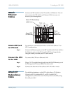
Step 3 Host Switch T1 Cables: All T1 cables from the rear of the CPX
shelf are properly connected to the DSX. All connections should be
made from the RJ48C patch panel, which in turn is connected via
the 25-pair cable to the RJ-21X port on the 12-port T1 transition
modules of the CPX shelf.
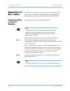
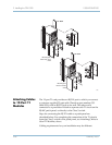
Step 4 STS-1 Cables: The CPX is connected to the Class 5 switch via 2
STS-1 cables connected from the STS-1 Splitter Assembly, and each
STS-1 module in the CPX connects to the Splitter Assembly with
two cables—Transmit and Receive— in a matched manner.
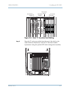
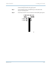
Apply Power After verifying CPX cabling, apply power to the CPX:
Step 1 Turn the circuit breaker on from the CPX rear panel.
Step 2 Verify that the CPX front panel POWER indicator is lit (directly
below the plug-in module cage).
Step 3 Verify that the INPUT indicators are lit on all power supplies.
Step 4 Verify that the fan in each power supply/fan module is running.