


February 2003 2-37
1000-A2-GN22-00 2. CPX-1000 Voice Services Platform Description
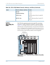
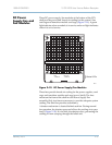
DC Power
Supply Fan and
Fan Modules
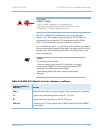
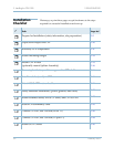
Three DC power supply/fan modules at the bottom of the CPX
shelf provide power and forced-air cooling for the system’s line
card cage and transition module card cage (Figure 2–19). A green
light indicates when a module is in service and a red light indicates
when it is out of service.
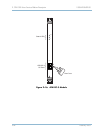
Figure 2–19. DC Power Supply/Fan Modules
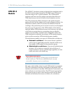
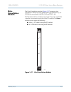
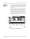
Three fans provide forced-air cooling for the power supplies, card
cage, and transition module card cage (rear of shelf). The fans
mount on the front of the shelf in each Power Supply Fan
assembly. Only two fans are necessary to provide adequate system
cooling. The third fan provides redundancy.
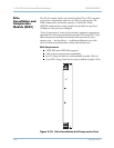
A shutter mechanism is located behind each fan. During normal
fan operation, the shutter opens and allows the cooling air to pass
freely (Figure 2–20). If a fan fails, the shutters close, preventing the
cooling air from escaping through the failed unit.
0070
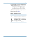
Status LEDs
OUT OF
SERVICE
IN
SERVICE