


2. CPX-1000 Voice Services Platform Description 1000-A2-GN22-00
2-14 February 2003
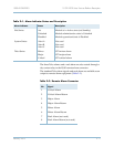
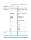
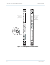
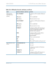
Table 2–3 lists the function of each control, port, and indicators.
Table 2–3. CP Module Controls, Indicators, and Ports
Card Controls, Indicators, and Ports Function
Call Processor (CP)
T64 1 ETHERNET
Connects to CP A module’s Ethernet
port
Link (green)
Link is established
ACT (Amber)
Ethernet circuit is in use
T64 2 ETHERNET
Connects to CP B module’s Ethernet
port
LINK (green)
Link is established
ACT (Amber)
Ethernet circuit is in use
10/100 BASE T Connects to MP card
COM 1 Not used
RST Resets the CP module and may reset
the shelf—DO NOT USE
ABT Not used
BFL Lights yellow when board fails
CPU Lights green when there is CPU
activity
CPCI Lights green when there is cPCI bus
activity
PCI Lights green when there is PCI bus
activity
USB 1 Not used
USB 2 Not used
Hot Swap Controller
(HSC)
PWR CP and HSC cards are powered
ERROR Lights when there is an HSC error