


February 2003 3-17
1000-A2-GN22-00 3. Installing the CPX-1000
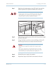
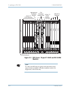
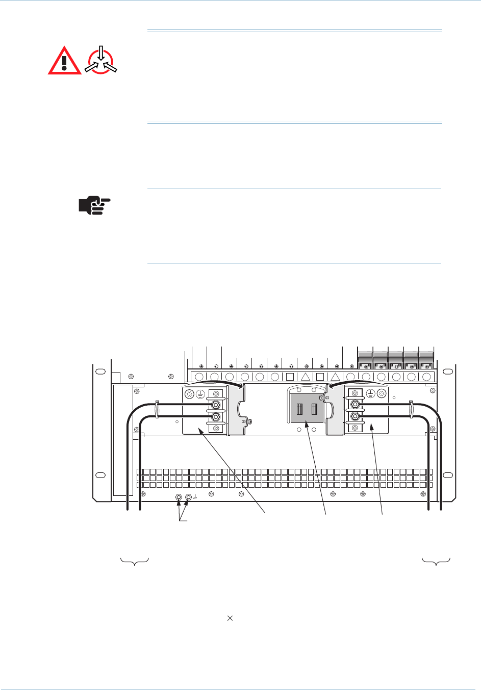
To connect plant battery power and ground to the CPX, follow
these steps:
Step 1 Terminate a #6 AWG frame ground wire in an LCC or LCD
compression lug (with two #10 screw holes).
Step 2 Using two 10-32 ¼-inch machine screws, attach a frame grounding
cable to the two rear panel ground points. Attach the other end of
this grounding cable to rack ground.
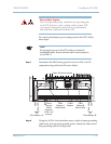
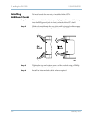
Electro-Static Caution
Use a wrist grounding strap, attached to the grounding jack
on the CPX enclosure, when working with the system. ESD
can seriously damage the printed circuit card assemblies
and solid-state components inside the CPX.
Note
Do not apply power to the CPX until you finish all
installation tasks. Ensure that the shelf circuit breaker is
set to OFF/0.
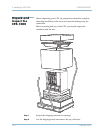
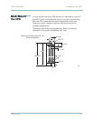
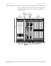
0069
16 15 14 13 12 11
7
9
6
810
54321
DC -48V
DC -48V
RTN
DC -48V
DC -48V
RTN
To
Plant Battery "A"
-48V RTN
-48V
To
Plant Battery "B"
-48V
-48V RTN
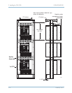
Plant
Battery A
Barrier Strip
Frame
Ground
Points
(requires
10-32 x 1/4"
screws)
Circuit
Breaker
Plant
Battery B
Barrier Strip
Open Protective Guards