


3. Installing the CPX-1000 1000-A2-GN22-00
3-16 February 2003
Mount the
Splitter
Assembly
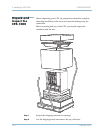
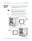
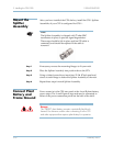
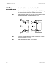
After you have installed the CPX shelves, install the STS-1 Splitter
Assemblies if your CPX is configured for STS-1. .
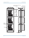
Step 1 If necessary, reverse the mounting flanges to fit your rack.
Step 2 Place the Splitter Assembly into position above the CPX.
Step 3 Using a slotted screwdriver, insert four 12-24 -inch pan head
screws to each flange to fasten the Splitter Assembly to the rack.
Step 4 Repeat these steps for each Splitter Assembly.
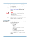
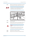
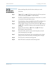
Connect Plant
Battery and
Frame Ground
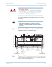
Power comes in to the CPX rear panel at the A and B plant battery
power strips. The A and B power legs each may be connected to
either of the power connection points on the back of the shelf.
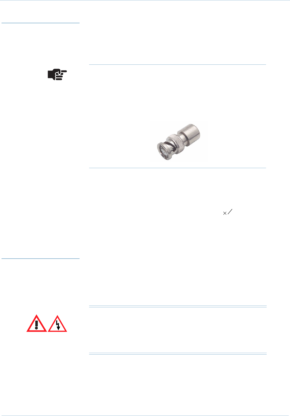
Note
The Splitter Assembly is shipped with 75 ohm BNC
terminators in place to prevent signal degradation.
These caps should be left in place until an STS cable is
connected, and should be replaced if the cable is
removed.
1
2
Danger
The –48VDC plant battery presents a potentially fatal shock
hazard. Use extreme caution when connecting it to the CPX
and other equipment that requires plant battery for operation.