


February 2003 3-23
1000-A2-GN22-00 3. Installing the CPX-1000
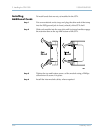
Verify
Hardware
Installation
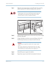
Before attaching cables, take this time to check your work:
Verify that:
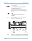
Step 1 The 48 VDC A and 48 VDC B terminals of the CPX rear panel are
wired to the plant battery
48V A and B branches.
Step 2 The RTN A and RTN B rear terminals are wired to the A (+) and B
(+) terminals of the plant battery source.
Step 3 Circuit breakers or fuses are installed for the CPX according to site
engineering plans at the plant battery branch circuit panel.
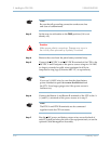
Step 4 Using a digital voltmeter, measure that plant battery is 48 VDC at
the
48 VDC A and RTN A (battery return) terminals on the CPX
rear panel.
Step 5 Measure that plant battery is 48 VDC at the 48 VDC B and
RTN B (battery return) terminals.
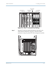
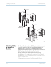
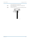
Step 6 Each card is fully seated in its slot on the front plane, and each
card’s mounting screws are tight.
Step 7 Each transition card (in back of the corresponding card) is firmly
seated in its slot, and each module’s mounting screws are tight.
Step 8 The CPX rack is connected to earth ground.
Step 9 Each CPX shelf is connected to rack (frame) ground.