


3. Installing the CPX-1000 1000-A2-GN22-00
3-30 February 2003
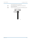
On the RJ-21X connector, the tip connectors are on the left; the ring
connectors are on the right. T1 circuits are numbered from 1
through 12, descending down from the top of the connector.
Circuit number 1 transmits on tip pin 1 and ring pin 26; it receives
on tip pin 2 and ring tip 27. The numbering and transmit receive
scheme continues to the bottom; pins 25 and 50 are unused. A
complete table of circuits, pin function and wire color by pin is
provided in
Appendix B, Pin Assignments and Indicators.
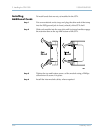
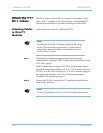
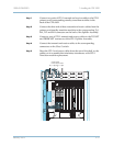
Step 3 Connect the T1/DS-1 spans to the T-1 transition modules in the
back of the CPX shelf.
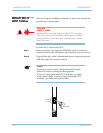
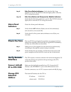
Attach the
STS-1 Cables
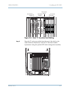
The CPX connects to the Class 5 switch via two STS-1 cables
connected from the STS-1 Splitter Assembly.
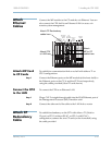
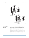
Each STS-1 module includes a corresponding STS-1 transition
module that is accessible from the rear of the shelf. Each STS-1
Transition module connects to the Splitter Assembly with two
cables, Transmit and Receive.
Table 3–1 describes the connectors functions.
Note
STS-1 cables require coaxial 75 plus or minus 5% cable
with BNC connectors on the CPX end for these
connections. To facilitate the connections, label each
cable by its destination port at the host Class 5 switch.
Table 3–1. STS-1 Cable Connections
Connection Function
TX1 Transmit cable to primary STS-1 Transition Card
To Net Transmit STS-1 cable to PSTN
TX2 Transmit cable to standby STS-1 Transition Card
RX1 Receive cable from primary STS-1 Transition Card
From Net Receive STS-1 cable to PSTN
RX2 Receive cable from standby STS-1 Transition Card