


3. Installing the CPX-1000 1000-A2-GN22-00
3-18 February 2003
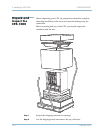
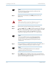
Step 3 Set the rear circuit breaker to the Off/0 position (if it is not
already off).
Step 4 Remove the cover from the plant battery terminal strip.
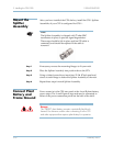
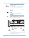
Step 5 Connect the 48 VDC A and 48 VDC B terminals of the CPX to the
48 VDC A and B outputs of the power source using two 14 AWG
(or larger), stranded or solid wires terminated in #10 size
compression ring lugs (Caltronics #RT-117, or equivalents).
Step 6 Connect the Return A and Return B terminals of the CPX to the A
(+) and B (+) terminals of the power source as in step 5.
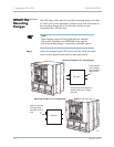
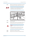
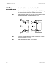
Step 7 Run the 48V power and battery return wires across the back of
each CPX shelf and along the side of the equipment rack, or use the
optional Cable Management Assembly.
Note
Be sure that all grounding connection surfaces are free
and clear of contaminants.
Caution
Make proper polarity connections. Damage may occur to
the circuitry when powered up if polarity is reversed.
Note
If you use 14 AWG wire, be sure that the plant battery
power distribution point is no more than 40 feet from
the CPX. Use a larger gauge wire if the power source is
further away.
Note
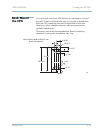
The RTN A and RTN B terminals are also connected
together inside the CPX enclosure.