


February 2003 5-5
1000-A2-GN22-00 5. Repair Procedures
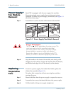
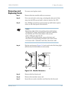
Installing the
Alarm Panel
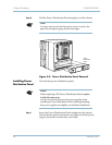
To install the Alarm panel, see Figure 5–2 and:
Step 1 Insert the alarm cable connector into header J4 on the alarm panel.
The cable connector and header are keyed—they fit together only
in one direction. The retaining clips close as the connector seats.
Step 2 Gently squeeze the retaining clips towards each other to ensure
that they are fully closed and that the connector is fully seated.
Step 3 Guide the tabs at the bottom of the panel into the chassis slots.
Step 4 Push the top of the alarm panel towards the top of the chassis and
secure the panel with the two captive screws provided.
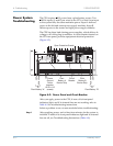
Power
Distribution
Panel
The Power Distribution Panel is not hot-swappable. Removing the
panel removes power from the the power supplies.
Removing Power
Distribution
Panel
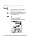
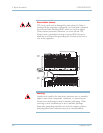
To install the Power Distribution Panel (see Figure 5–3):
Step 1 Shut down the CPX. If the system is configured as a dual-CP
system, ensure that both domains are shut down.
Step 2 Turn the system power off (see Recommended Power Off on page
5-1).
Step 3 Remove the power cord from the Power Distribution Panel.
Step 4 Loosen the four captive screws on the corners of the panel.
Voice/Data Interruption
Removing power shuts down the CPX-1000. Shutting down
the CPX-1000 disrupts all calls and interrupts service.
Note
You do not need to remove the power supplies to
remove the Power Distribution Panel.