


3. Installing the CPX-1000 1000-A2-GN22-00
3-26 February 2003
Attach the T-1/
DS-1 Cables
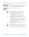
The CPX connects to host Class 5 switches via multiple T1/DS-1
spans. Each T-1 module in the CPX includes a corresponding T1
transition module that is accessible from the rear of the shelf.
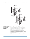
Attaching Cables
to Octal T1
Modules
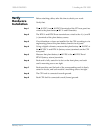
Connect the host switch T1 cables to the CPX:
Step 1 Following the installation engineering and provisioning
documentation, map the T1/DS-1 connections from the host switch
to T1/DS-1 groups.
Each T1 connection is assigned a T1/DS-1 group number and an
individual connection number, such as 1-1. T-1 #1 must connect to
T1/DS-1 #1 at the Class 5 switch, etc. A T1/DS-1 interface group is
the logical administrator of the T1s. The minimum number
required for an interface group is 2.
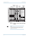
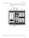
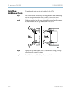
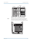
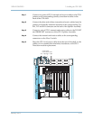
Step 2 Connect the T1/DS-1 spans to the T-1 transition modules in the
back of the CPX shelf.
Note
T1 cables for the Octal T1 module require RJ-48C plugs
on the CPX end for these connections. To facilitate the
connections, label each cable by its destination port at
the host Class 5 switch.
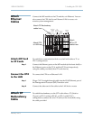
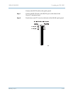
Note
T1 jacks are numbered 1–8 or 1–12 (#1 is located at the bottom).