


February 2003 2-11
1000-A2-GN22-00 2. CPX-1000 Voice Services Platform Description
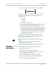
The three Telco alarms and a rack alarm are also routed through a
dry contact relay to the RJ-45 remote alarm connector.
The standard Telco alarm signals and rack alarm are available as an
output to remote alarm equipment (Table 2–2).
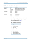
Table 2–1. Alarm Indicator Status and Description
Alarm Indicator Status Description
Slot Status Act
Unlocked
Disabled
Module is in Active state (not Standby)
Module administrative state is Unlocked
Module operational state is Disabled
System Status Alert A
Alert B
Alert C
Not used
Not used
Not used
Telco Status Minor
Major
Critical
CPX minor alarm
CPX major alarm
CPX critical alarm
Table 2–2. Remote Alarm Connector
Pin Signal
1Critical Alarm
2 Critical Alarm Return
3Major Alarm
4Major Alarm Return
5Minor Alarm
6Minor Alarm Return
7 Rack Alarm (not used)
8 Rack Alarm Return (not used)