


2. CPX-1000 Voice Services Platform Description 1000-A2-GN22-00
2-10 February 2003
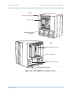
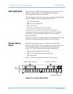
CPX-1000 Shelf Each CPX shelf is 12 RU (21 inches) high and 17 inches deep. The
shelf can mount in either a 19-inch Electronic Industries
Association (EIA) rack or a 23-inch rack.
The CPX shelf is a forced-air cooled Network Equipment Building
Standard (NEBS) Level 3-compliant platform with:
16-slot midplane
DC power input panel
Alarm panel
Three hot-swappable power supplies
The midplane is the interconnect for all 16 slots, power
distribution, and alarm signal distribution. The CPX midplane
accepts line cards, processing modules, and rear mounted
transition modules.
The power supplies (including integral fan assemblies) are located
below the card cage (accessible from the front of the shelf).
System Alarm
Panel
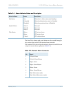
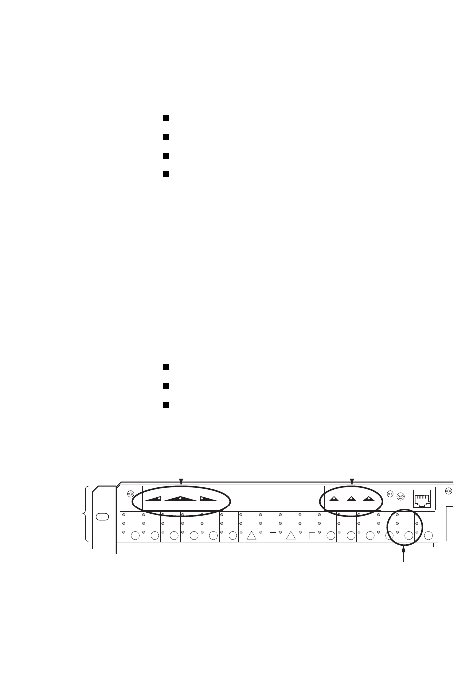
The CPX alarm panel is located on the top front of the shelf.
Indicators display the current operating status of the shelf and an
alarm connector outputs to remote Telco alarm equipment
(Figure 2–5). The CPX includes three types of indicators:
Slot Status indicators for all 16 slots
System Status indicator for system status
Telco alarms
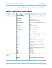
Table 2–1 lists the description and status of each group.
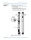
Figure 2–5. System Alarm Panel
0233-01
Alarm
Panel
1
23456
7
8
9
11 12 13 14
15
16
DISABLED
UNLOCKED
ACT
DISABLED
UNLOCKED
ACT
DISABLED
UNLOCKED
ACT
DISABLED
UNLOCKED
ACT
DISABLED
UNLOCKED
ACT
DISABLED
UNLOCKED
ACT
DISABLED
UNLOCKED
ACT
ALERT A ALERT B MINOR
SYSTEM ALERTS TELCO
ALERT C
DISABLED
UNLOCKED
ACT
DISABLED
UNLOCKED
ACT
DISABLED
UNLOCKED
ACT
DISABLED
UNLOCKED
ACT
DISABLED
UNLOCKED
ACT
DISABLED
UNLOCKED
ACT
DISABLED
UNLOCKED
ACT
DISABLED
UNLOCKED
ACT
DISABLED
UNLOCKED
ACT
MAJOR CRITICAL
ALARM
10
System Status Indicators Telco Alarm Indicators
Slot Status Indicators