


Pelco Manual C1515M-A (11/01) 11
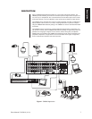
INSTALLATION
Unpack and inspect all parts carefully. The following parts are supplied:
1 CM6800 Switcher/Controller
4 10-32 x .750-inch pan head screws
4 .500” OD nylon washers
1 Power cord
4 6-foot (1.8 m) straight data cables with RJ-45 connectors
1 6-foot (1.8 m) reversed data cable with RJ-45 connectors
4 RJ-45 wall block terminals
MOUNTING
1. Select a suitable location for the CM6800. It occupies 5.25 inches (13.34 cm) of
vertical space, or three rack units (RUs), in a universal mount. The CM6800 must be
within 6 feet (1.8 m) of a suitable electrical outlet.
Follow proper installation practices and leave 1 RU above and below the
CM6800 for ventilation.
Do not connect the power until the installation is complete. Refer to the
System
Start-Up
section.
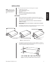
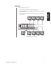
2. The CM6800 is shipped with the rack ears installed at the front. Reposition as needed
for your application. If the ears are not required, remove them.
NOTE:
There are no user-
serviceable parts inside this
unit. Only authorized service
personnel may open the
unit.
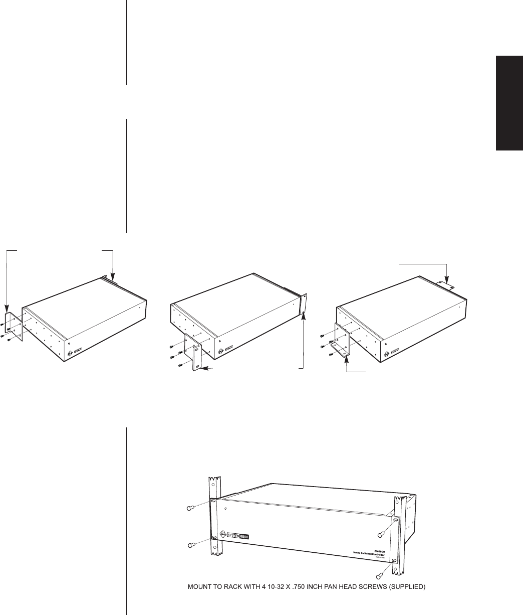
Figure 2. Installing Rack Ears
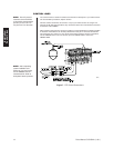
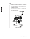
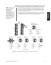
3. Use supplied pan head screws and washers to mount the CM6800 in a standard 19-
inch (48.26 cm) equipment rack or wood or sheet metal screws to mount against a flat
surface, according to your installation requirements.
Figure 3. Mounting the CM6800 Matrix Switcher/Controller
00615
POSITION BRACKETS FOR
RACK MOUNTING (FRONT)
POSITION BRACKETS FOR
FLUSH MOUNTING
(WALL AND TABLE TOP)
POSITION BRACKETS FOR
RACK MOUNTING (REAR)
NOTE: EACH CM6800 COMES
WITH 2 RACK EARS
POSITION BRACKETS FOR
UNDER-TABLE MOUNTING
00624
Installation