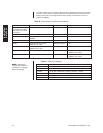
Pelco Manual C1515M-A (11/01) 29
CONNECTING A PC
The CM6800 provides PC-based setup and programming software that facilitates complete
switcher programming and configuration. Refer to the CM6800-MGR Quick Start Guide for
instructions on using the software.
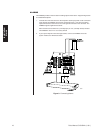
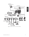
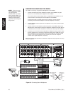
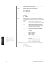
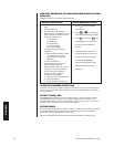
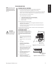
Connect a PC to the CM6800 to access the CM6800-MGR software or to download
upgrades to the software. You can connect a PC to the CM6800 through either a DB9 port
or an RJ-45 port. You cannot use both ports simultaneously.
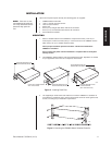
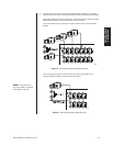
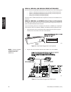
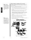
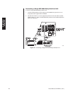
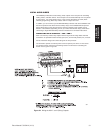
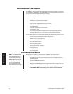
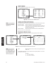
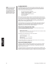
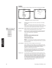
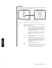
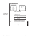
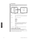
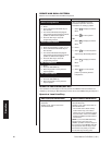
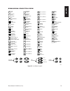
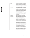
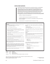
1. Using a null modem cable (user-supplied), plug one end into the DB9 COM 1 port on
the PC.
2. Plug the other end of the cable into the DB9 COM 1 port of the CM6800.
NULL MODEM CABLE
CM6800 COM 1
DB9 PIN-OUTS
PIN 2 = RX IN
PIN 3 = TX OUT
PIN 5 = GND
PIN 5PIN 1
PIN 6
PIN 9
PC COM 1
DB9 PIN-OUTS
PIN 2 = RX IN
PIN 3 = TX OUT
PIN 5 = GND
00613
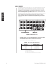
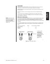
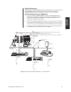
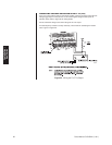
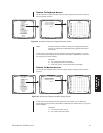
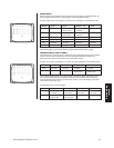
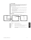
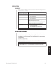
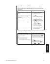
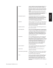
CM6800 COM 1
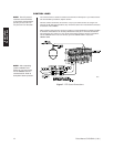
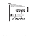
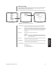
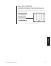
RJ-45 PIN-OUTS
PIN 1 = RX IN
PIN 5 = GND
PIN 8 = TX OUT
PC COM 1
DB9 PIN-OUTS
PIN 2 = RX IN
PIN 3 = TX OUT
PIN 5 = GND
RJ-45 WALL BLOCK
AND STRAIGHT CABLE
SUPPLIED WITH CM6800
2
3
4
5
6
7
1
8
MODIFIED NULL MODEM CABLE
(USER-SUPPLIED)
PC COM 1
CM6800 COM 1
00992
Figure 21. PC Connection to DB9 Port
OR
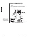
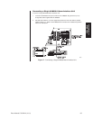
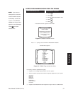
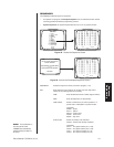
1. Using a modified null modem cable (user-supplied), connect the DB9 COM 1 port on
the PC to an RJ-45 wall block (supplied with the CM6800 Matrix Switcher).
The modified null modem cable should be cut at one end, so that you can connect the
wires directly to the wall block pins.
2. Using a 6-foot (1.8 m) data cable (supplied with the CM6800 Matrix Switcher), connect
the wall block to the RJ-45 COM 1 port of the CM6800.
Figure 22. PC Connection to RJ-45 Port
NOTE:
You can also
connect an ASCII device
through COM 1, 2, 7, or 8.
Using an ASCII device
through COM 1 requires a
change in serial port
settings. Refer to the
Programming
section for
instructions.
Installation:
PC Connection