


82 Pelco Manual C1515M-A (11/01)
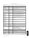
Pattern A pattern is a user-defined, viewable camera path with a
definite beginning and end. The pattern can consist of any
standard pan and tilt or lens command. Once defined, the
pattern is easily activated by a system operator or through
an automated event. The pattern will run continuously until
it is deactivated. The number and time length of patterns
varies with different positioning systems.
Physical input A number representing an actual BNC camera input on
the rear panel of the matrix switcher. This number cannot
be changed.
Preset A preset allows operators to direct a PTZ (camera
positioning system) to move to a predetermined scene on
keyboard command or as a result of an alarm. In addition
to moving the camera, a descriptive title can appear on
the screen. The type of camera positioning system
determines the number of presets available.
Priority control This is the level of priority a system keyboard has to
control a PTZ camera positioning system and to access
CM6800 Matrix Switcher on-screen programming menus.
PTZ This is a camera positioning system with pan, tilt, and
zoom capabilities.
Random scan This is a camera scan moving in a random pattern.
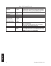
RJ-45 wall block This is a wall block with eight terminals for connecting
RS-232, RS-422, and RS-485 communication lines. (This
is Pelco part number CON12J00820360Z.)
RS-232 This is an Electronics Industry Association (EIA) interface
standard used for data communication; the normal
connection distance is 50 feet (15 m). Pelco uses this
standard for communication from a controller to a PC or
RS-232 network. The Pelco three-wire connection
provides one wire for transmit, one wire for receive, and
one wire for common.
RS-422 This is an Electronics Industry Association (EIA) interface
standard. Pelco uses this standard for communication
from a controller to one or more camera receivers (on the
same line); the maximum recommended distance is 4,000
feet (1,219 m).
The four-wire connection provides two wires for transmit
and two wires for receive. Pelco receiver/driver
communication uses only the two transmit wires
(commands are sent from the controller to the receiver
only; the receiver does not “talk” back to the controller).
Pelco keyboard communication uses all four wires.
NOTE:
The electrical communication scheme used by
Pelco is a direct-coupled method, not an AC-coupled
method. Therefore, if the ground potential of the wire at its
two end points is different (other than zero volts), an
additional wire is required as a ground.
Glossary