


Pelco Manual C1515M-A (11/01) 59
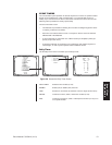
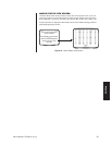
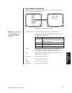
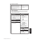
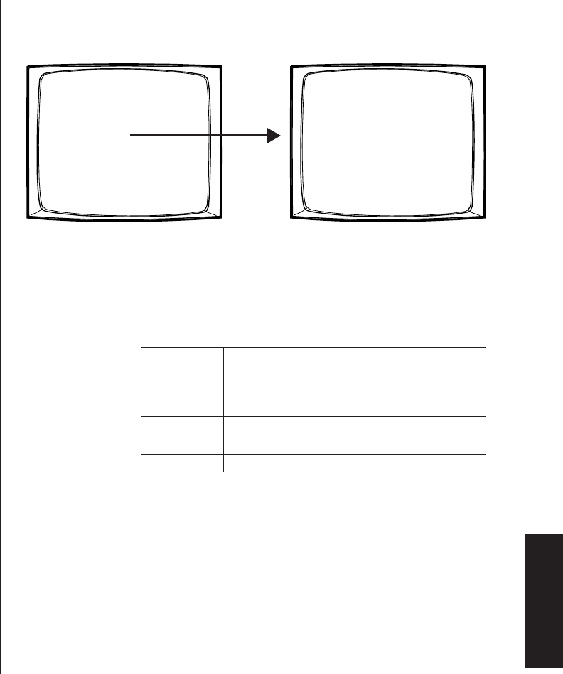
Figure 47. Access the Port Screen
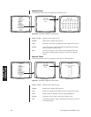
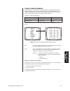
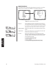
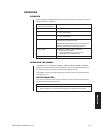
SET SERIAL PORT: Select the number of the desired Serial Port/COM port (01-10).
The serial port numbers correspond to the communication ports on
the CM6800 rear panel as follows:
Serial Port Input on CM6800 rear panel
01 COM 1
NOTE:
COM 1 can be accessed through a DB9
input or an RJ-45 port.
02-08 COM 2-8 RJ-45 inputs
09 PTZ-A control input
10 PTZ-B control input
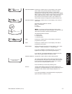
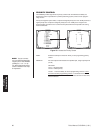
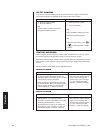
DEVICE: Select the device connected to the COM port; the values in the
TYPE, BAUD RATE, PARITY, DATA BITS, and STOP BITS fields
change to the settings appropriate for the specific device.
TYPE: If necessary, and if allowed, select the desired communication type
(RS-232, RS-422, or RS-485).
BAUD RATE: Select the desired baud rate.
PARITY: Select the desired parity type.
DATA BITS: This value cannot be changed.
STOP BITS: This value cannot be changed.
PELCO SWITCHER
MODEL CM6800
MAIN MENU
1 CAMERA
2 LOGICAL CAMERA
3 MONITOR
4 ACCESS
5 TIME & DATE
6 PORT
7 PRIORITY
8 SEQUENCE
9 MACRO
10 ALARM CONTACTS
11 EVENT TIMER
12 SET AUXILIARY
13 SET PASSWORD
14 ABOUT CM6800
ENGLISH
RETURN
00654
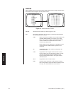
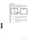
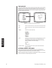
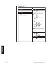
SET SERIAL PORT 05
DEVICE: KBD300
TYPE: RS485
BAUD RATE: 9600
PARITY: ODD
DATA BITS: 8
STOP BITS: 1
RETURN
00657
NOTE:
In the programming
screens “KBD300” is used
to refer to the KBD100,
KBD200, and KBD300
keyboards.
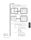
PORTS (SERIAL/COM PORTS)
Use the Port screen to configure the settings for each device connected to a Serial/COM
port on the rear panel of the CM6800.
Port
Programming