Pelco Manual C1515M-A (11/01) 47
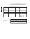
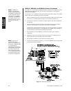
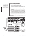
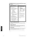
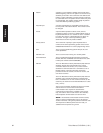
Video Loss Alarm
You can program the CM6800 to detect video loss from any camera input and indicate the
loss through alarm mode – the alarm icon and a “V” (for video loss) appear on system
monitors as specified by alarm group assignment.
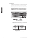
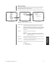
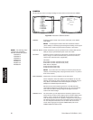
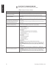
Use the Video Loss screen to configure the system to display an alarm based on video loss.
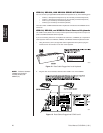
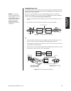
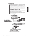
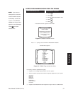
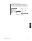
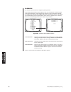
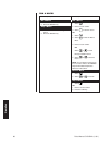
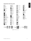
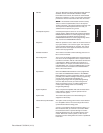
PELCO SWITCHER
MODEL CM6800
MAIN MENU
1 CAMERA
2 LOGICAL CAMERA
3 MONITOR
4 ACCESS
5 TIME & DATE
6 PORT
7 PRIORITY
8 SEQUENCE
9 MACRO
10 ALARM CONTACTS
11 EVENT TIMER
12 SET AUXILIARY
13 SET PASSWORD
14 ABOUT CM6800
ENGLISH
RETURN
00654
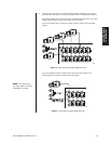
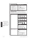
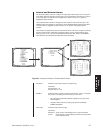
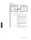
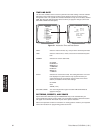
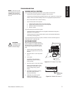
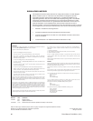
Figure 35. Access the Video Loss Screen
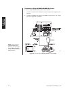
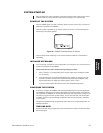
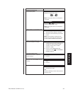
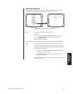
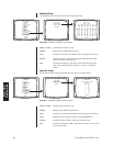
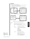
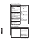
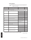
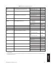
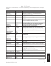
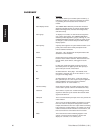
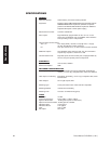
PHYSICAL INPUT: Select the physical input number; the logical camera number associ-
ated with the specific physical input appears on the screen below.
ENABLE: Enable video loss detection for the specific video input by selecting ON
(Default = OFF); to complete the enable process, you must also assign
the alarm contact to an alarm group (refer to the GROUP ENABLE
description).
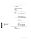
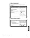
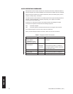
ACK TYPE: Select the video loss alarm clearance type.
OPTIONS:
MANUAL = alarm must be acknowledged from a system keyboard
AUTO = alarm will time out automatically after the interval specified
in the TIME OUT field
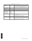
TIME OUT: Enter the amount of time (0-99 seconds) alarm remains active after the
video has been restored (AUTO alarms only).
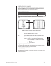
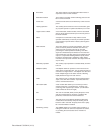
CAMERA 0001: The logical camera number associated with the physical input specified
in the PHYSICAL INPUT field appears here.
GROUP ENABLE: Assign the video loss alarm to one or more alarm groups (A through H).
OPTIONS:
Y = include in group
N = do not include in group
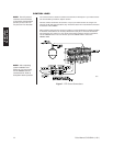
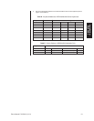
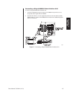
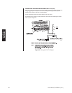
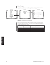
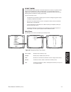
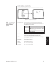
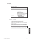
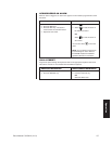
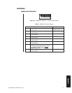
ALARM CONTACTS
1 INTERNAL CONTACT
2 EXTERNAL CONTACT
3 VIDEO LOSS
4 ALARM GROUP
RETURN
00642
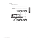
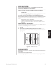
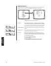
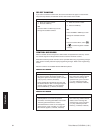
VIDEO LOSS MENU
PHYSICAL INPUT:
ENABLE: OFF
ACK TYPE: MANUAL TIME OUT: 10
CAMERA 0001
GROUP ENABLE
ABCDEFGH
NNNNNNNN
RETURN
00663
Video Loss
Programming