


2 – Using SANbox Manager
Using the Faceplate Display
2-22 59048-02 A
Q
2.13
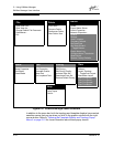
Using the Faceplate Display
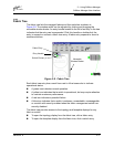
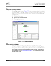
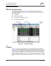
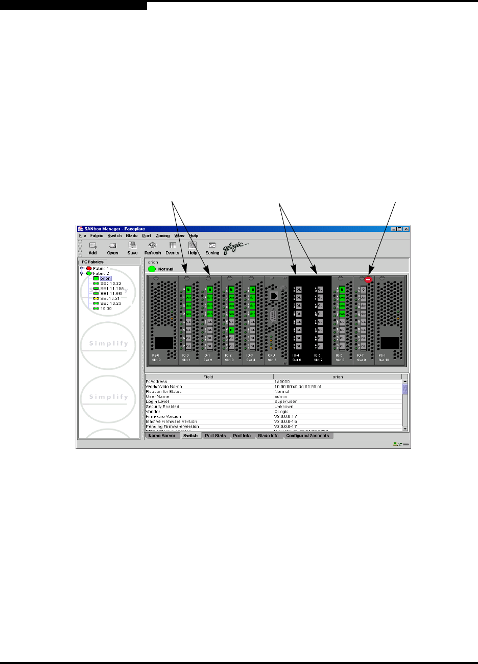
The faceplate display shown in Figure 2-11 displays the switch name and
operational state, and port status. Consider the following functional elements of
the faceplate display:
I/O blades
Port views and status
Working with I/O blades and ports
Faceplate data windows
Figure 2-11. Faceplate Display
2.13.1
I/O Blades
Figure 2-11 shows how slots appear in the faceplate display with and without
installed I/O blades. I/O blade failure status is indicated by a status icon as shown
in Figure 2-11. The SANbox2-64 switch numbers its slots from 0–10 from left to
right. I/O blades occupy slots 1–4 and 6–9. Ports on an I/O blade are numbered
from 0–7 from top to bottom in slot 1, 8–15 in slot 2, and so on to 56–63 in slot 9.
The Blade Info data window assigns blade numbers 0–7 to slot numbers 1–4 and
6–9.
Empty Slots
I/O Blades
I/O Blade
Status