


Appendix: Sample Configurations A-3
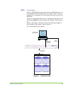
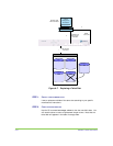
STEP 1. ATTACH CABLES
Attach an HSSDC-DB9 fibre channel cable from your JBOD appliance to one
of the storage ports on the back panel of the V-Switch. See #1, Figure
A-1.
Depending on your appliance, you need to plug a terminator into one of the
JBOD ports.
Attach the included RS232 cable from your management/host station to the
console port (Console) on the back panel of the V-Switch. See #2, Figure
A-1.
Attach an RJ45 copper 1 Gbit Ethernet cable to the Ethernet port Eth1 on
the front panel of the V-Switch. See #3, Figure
A-1.
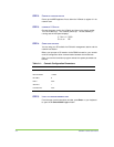
Your network should mimic Figure
A-1.
10232
Client
s
Disk 1 Disk 2
Disk 4Disk 3
V Switch
Manager and
Host Station
RS232
Connection
Fibre Channel
Connection
Windows 2000
Microsoft Initiator
1
2
1 Gbit Ethernet,
RJ45 Copper
Connection
3
JBOD 1
Figure A-1. System Overview