


5-4 SANRAD V-Switch CLI User Manual
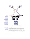
RAID controller are simultaneously exposed through all ports connected
to both V-Switches for the V-Switches to provide high availability during a
V-Switch failover.
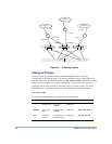
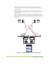
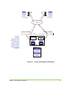
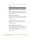
In Figure 5-2, V-Switch 1 has gone off-line. V-Switch 2 activates V-Switch 1’s IP
address and takes over exposure of Volume 1 to Host 1, represented by the
orange dashed line.
Host 1 continues to access Volume 1 through the same IP address as it did
before its V-Switch went off-line. Host 1 has no way of knowing that its regular
V-Switch is off-line. Host 1’s storage performance is not impacted by the off-
line V-Switch.
10268
Cloud
IP SAN
IP1-inactive
IP2-inactive
IP2-active
IP1-active
Tower box
Host 2
iSCSI
initiator
Vol 2Vol 1
Tower box
Host 1
iSCSI
initiator
V Switch 1 V Switch 2
Disk 1 Disk 2
Disk 4Disk 3
iSCSI Target 2
wwui2
iSCSI Target 1
wwui1
Vol 2
LU0
Vol 1
LU0
IP1,Target 1 IP2,Target 2
JBOD
Figure 5-2. Re-routing Storage Access with Off-line V-Switch