


Chapter 5: V-Switch Cluster Configuration 5-3
.
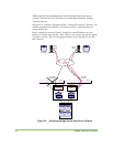
When creating a
cluster, it is
recommended that
the same port on
each V-Switch is
used to connect to
the same storage
device. This
increases the chance
of the storage device
receiving the same
default storage
number on both V-
Switches during their
auto-discovery
cycles. This, in turn,
makes cluster
configuration easier.
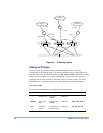
10267
Cloud
IP SAN
IP1-active
IP2-inactive
IP2-active
IP1-inactive
Tower box
Host 2
iSCSI
initiator
Vol 2Vol 1
Tower box
Host 1
iSCSI
initiator
V Switch 1 V Switch 2
Disk 1 Disk 2
Disk 4Disk 3
IP1,Target 1 IP2,Target 2
iSCSI Target 2
wwui2
iSCSI Target 1
wwui1
Vol 2
LU0
Vol 1
LU0
JBOD
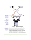
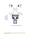
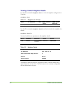
Figure 5-1. V-Switch Cluster Configuration
When working in a
cluster, the V-Switch
can support a
maximum of 100
portals: 50 active
and 50 inactive.
Clusters also provide high availability in the event of V-Switch failover.
Each network port on the V-Switch is configured with its own active, or
functioning, IP addresses as well as inactive, or dormant, neighbor IP
addresses. If one V-Switch goes off-line, the remaining V-Switch activates
its neighbor’s IP addresses. The hosts continue to access volume targets
through the same IP address without sensing that their ‘regular’ V-Switch
has gone offline or noticing any impact on storage performance.
When working with RAID controllers, it is imperative that all LUNs in the