


2-6 SANRAD V-Switch CLI User Manual
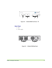
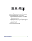
STEP 1. PLACE THE V-SWITCH 2000 RIGHT SIDE UP ON A SECURE FLAT
SURFACE NEAR THE RACK
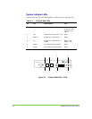
STEP 2. ATTACH THE LEFT FRONT L-BRACKET
The left front L-bracket is the wide L-bracket with two round openings for
air intake.
Attach it with four of the included screws. The bracket sits directly against
the V Switch.
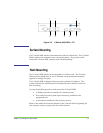
STEP 3. ATTACH THE RIGHT FRONT L-BRACKET
There are two types of right front L-brackets, depending on if the V-Switch
is single or dual-mounted.
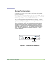
For single-mounting, use the long arm L-bracket to span the space from the
V-Switch to the rack. Attach it with four of the included screws.
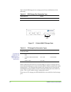
For dual-mounting, use the short L-bracket on both V-Switches. Then place
the two V-Switches side by side with the lip of the left V-Switch L-bracket in
front of the lip of the right V-Switch L-bracket. Attach the two V-Switches
by inserting two screws through the front holes of the overlapping L-
brackets.
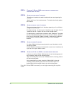
STEP 4. ATTACH THE REAR L-BRACKET
If a single V-Switch is being mounted, attach the rear L-bracket to the left
side of the V-Switch.
If dual V-Switches are being mounted, attach a second rear L-bracket to the
right side of the right V-Switch as well.
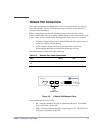
STEP 5. ATTACH THE V-SWITCH 2000 TO THE RACK MOUNTING POSTS
Insert the rear of the V-Switch 2000 between the rack mounting posts until
the L-bracket(s) touch the rack mounting posts.
Align the mounting holes on the rear L-brackets with the mounting holes on
the rack mounting posts.
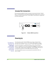
Using screws that you provide, attach the V-Switch 2000 to the rack
mounting posts by screwing two screws on each side through the L-
brackets and into the threaded holes in the rack mounting posts.
Once the V-Switch 2000 is mounted, you can begin connecting the requisite
cables.