


Appendix: Sample Configurations A-17
10234
Disk 1 Disk 2
Disk 4Disk 3
1
2
Network B
212.199.43.70
Initiator Target:
212.199.43.56
Eth 1: 100.100.100.2 Eth 2: 212.199.43.56
1 Gbit Ethernet,
RJ45 Copper
Connections
R
10.10.0.0
3
Windows 2000
V Switch
Management
Station
Microsoft
Initiator
Fibre Channel
Connection
Tower box
Tower box
Host 1
IP address:
10.10.1.1
Tower box
Host 2
IP address:
212.199.43.90
IP address:
100.100.100.1
t
LAN A
JBOD 1
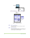
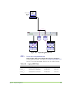
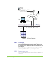
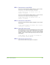
Figure A-9. IP Routing Topology
STEP 1.
ATTACH CABLES
Attach an HSSDC-DB9 fibre channel cable from your JBOD appliance to one
of the storage ports on the back panel of the V-Switch. See #1 in Figure
A-9. Depending on your appliance, you need to plug a terminator into one
of the JBOD ports.
Attach an RJ45 copper 1 Gbit Ethernet cable from the Ethernet port Eth1
on the front panel of the V-Switch to your management station.
STEP 2. POWER UP STORAGE DEVICE
Power up the JBOD appliance first to allow the V-Switch to register it in its
network scan.