


Chapter 3: Installing the V-Switch 3000 3-5
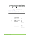
STEP 1. ATTACH THE REAR MOUNTS
Using screws that you provide, attach the rear mounts to the back
mounting posts so that the length of each mount is parallel to the floor and
extends forward into the rack space.
The lip of each mount is at the bottom and facing inward toward the
opposite rear mount.
The rear of the V-Switch 3000 will be supported from underneath on these
lips.
STEP 2. PLACE THE V-SWITCH 3000 RIGHT SIDE UP ON A SECURE FLAT
SURFACE NEAR THE RACK
STEP 3. A
TTACH THE L-BRACKETS ON BOTH SIDES OF THE CHASSIS
Use the ten screws included in the accessory packet to attach the L-
brackets to the chassis.
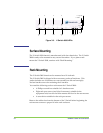
STEP 4. INSERT THE V-SWITCH 3000 INTO THE RACK
This step works best
with two people.
This step works best with two people: one at the rear of the rack coordinating
the V-Switch/mount connection and one at the front of the rack inserting the V-
Switch.
Slide the V-Switch 3000 into the rack making sure to position the V-Switch
3000 to rest on the rear mounts.
The rear mounts may turn inward slightly before the V-witch 3000 is
inserted. If the V-Switch does not enter easily, push the mount lips
outward slightly while inserting the V-Switch 3000.
Insert the rear of the V-Switch 3000 until the L-brackets touch the rack
mounting posts.
STEP 5. ATTACH THE V-SWITCH 3000 TO THE RACK MOUNTING POSTS
Align the mounting holes on the L-brackets with the mounting holes on the
rack mounting posts making sure that the L-brackets are the same height
as the rear mounts.
Using screws that you provide, attach the V-Switch to the rack mounting
posts by screwing two screws on each side through the L-brackets and into
the threaded holes in the rack mounting posts.
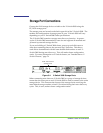
Once the V-Switch 3000 is mounted, you can begin connecting the requisite
cables.