


2-5
Powering Up
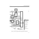
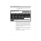
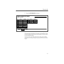
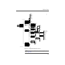
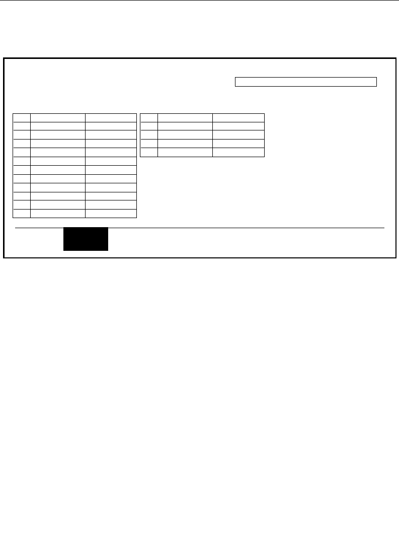
3. Press the UPPER BOARDS soft button.
This menu shows what slots in the upper card cage (Bay A) have
modules installed, and the format and assembly/version number
for each installed module.
You may wish to refer back to this menu when you are setting
parameters for analog and digital outputs and RGB chroma keyer
inputs.
SLOT
1
2
3
4
5
6
7
8
9
10
11
12
BOARD
RGB CK IN
RGB CK IN
RGB CK IN
DIG OUT-SER
ANLG OUT
DIG OUT-PAR
VERSION
068922-00C
068922-00C
068922-00C
068931-00F
068929-00F
068930-00C
SLOT
13
14
15
16
17
BOARD
DIG OUT-PAR
ANLG OUT
VERSION
068930-00C
068929-00F
INSTALLATION INFO MENU
status / install info
UPPER
BOARDS
LOWER
BOARDS
MODEL 3000-3 SOFTWARE VERSION: 5.0
MAIN
BOARDS