2-38
Section 2 — Startup & Configuration
For a particular studio session, three Kaleidoscope channels could
be acquired from the pool in the order D, E, A, which would be
logical channels 1, 2, 3. This mapping information is passed from
the DPM to the switcher via the control connection. Switcher
output routing ensures that the logical channels 1, 2, 3 appear to
the user on logical aux buses 1, 2, 3 and switcher input routing
ensures that DPM logical channels 1, 2, 3 appear on the
crosspoints configured for these logical channels. For the above
configuration, the selection of CHANNEL ROUTING in the DPM
Setup Menu should be set to BOTH.
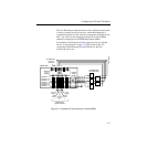
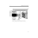
There are circumstances where output routing is not desirable. For
example, the DPM may have more than 5 channels. In that case, a
router or patch panel may be inserted between the switcher and
Kaleidoscope (Figure 2-4). In this example, switcher output
routing is turned off, so the menu selection for
CHANNEL
ROUTING
in the DPM Setup Menu should be set to SWR IN. This
still provides the return video from the switcher being on a
consistent crosspoint.


