


2-34
Section 2 — Startup & Configuration
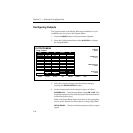
Configuring a DPM
Digital Picture Manipulators (DPMs) are external video devices
connected to the switcher. In this discussion, reference is also
made to DPM levels, which are E-MEM levels into which DPM-
associated information is learned. The combined system
capabilities of the switcher and DPMs depend on:
■ The video connection
■ The capabilities of the DPM
■ The control connection
It is not necessary to have a control connection from the switcher
to a DPM; however, the highest level of system integration is
achieved where there is a control connection.
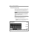
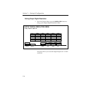
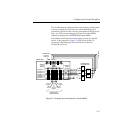
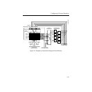
Video Connection (Aux Buses and Return Inputs)
A normal video signal path consists of an aux bus output from the
switcher feeding a DPM input and the DPM output returned to a
switcher input which is mapped to a switcher source select
button.
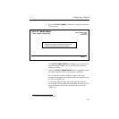
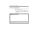
The video path through a DPM introduces a video delay into the
system. For example, Kaleidoscope introduces a 2-field video
delay. It is most important that this delay be set correctly in the
DPM Setup Menu if Effects Send is to be used.
NOTE:
If the video delay is not set correctly, there will be a glitch in the
video upon entering Effects Send mode.